|
Steve Ball What am I doing here? I gave a presentation at the 2019 European CLA summit titled “Applying a SOLID Framework for Cleaner Code”. The slides can be found on the Composed Systems website. I had a great time at the Summit and it was great to meet and talk about LabVIEW with the hundreds of CLAs who attended. I made a large open-source demo project for the presentation that I’d like to expand on and give more design detail. 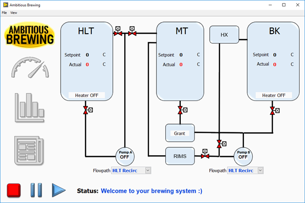 Demo Project Selection As an experienced homebrewer, I picked an automated home brewing system as a demo project. There are some open source projects like The Electric Brewery and CraftBeerPi that are similar, along with a plethora of PLC-based commercial offerings. The hardware complexity is relatively simple, with a few temperature sensors, heating elements, and assorted pumps and valves. There are a half dozen brewing steps that always run in the same sequential order, limiting the control complexity. The Challenge With these existing open source and commercial solutions, is it possible to create a fully featured, single board system with a rich user interface and feature set while keeping the cost about the same? Could it be configurable enough to work on systems with different plumbing configurations? Could it be done with LabVIEW? In my opinion, the answer is YES! 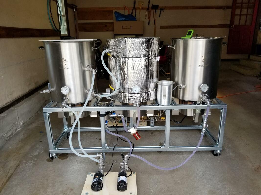 The 20 gallon homebrewing system before automation Making it Real I’m working with a friend to turn his 20 gallon, propane-fired homebrewing system into an automated brewing system. This will involve purchasing solenoid valves and swapping the propane burners out for electric resistive elements. I’ve selected a single board UDOO x86 computer to act as the brain of the operation. It has an Arduino-compatible module with GPIO onboard. Its low cost and integrated DAQ makes it a good match for a hobbyist project like this one. I’ll include a full parts list in the source code as we build the system. The Brewing Process The system consists of three vessels: the Hot liquor tank (HLT), Mash Tun (MT), and Boil Kettle (BK). In the current system, the hoses are moved manually depending on the brewing step. The steps are as follows: Preheat – The water in the HLT is heated and maintained at the strike temperature. Mash – the water is pumped into the MT where it steeps a barley tea called wort. The wort drains into a grant and is then pumped through a heat exchanger in the HLT to maintain temperature and recirculated into the MT. Lauter – The mash tun drains into the grant and the wort is pumped into the boil kettle. Boil – The wort is then boiled and additions like hops are added at scheduled intervals. Cool – The wort is pumped through a plate chiller and is cooled to near ambient. At this point the wort is done and can be drained from the system into the primary fermentation vessel and the yeast can be pitched along with any dry hop or other post-boil additions. Why automate a homebrewing system? Adding controls and instrumentation to the system adds cost and complexity. Brewers have been making beer without any of this for literally thousands of years. What are the advantages that this brings? First, controlling the temperatures precisely aids in the repeat-ability of the recipe, as the temperature of the mash controls the activation rate of the starches and sugars in the barley. This leads to the density, or original gravity measurement, which effects everything from alcohol content to body and mouth feel of the finished brew. Most home brewers use a step mash of one temperature. Advanced home brewers and professionals can use a multi-step mash, with rests at several temperatures to get a specific and more complex wort. Automating this step takes out the manual work of controlling the temperature and timing, so you can get a great mash every time. The Framework For this project I selected the Composed Systems MVA Framework. MVA stands for Mediated Viewable Actors. Not only did I choose it because it is the subject of the presentation, but it is the daily driver that I use every day for my clients. Ethan Stern did a great job following SOLID design principles while adding two critical pieces on top of NI’s Actor Framework: A mediated message bus and Model-View-ViewModel design pattern. 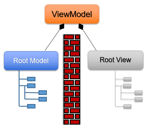 Separation of Concerns The most fundamental design principles in my mind are how to separate my user interface code from the model/business logic in the application, and how to bind these two entities together. The MVA framework provides this functionality through the use of abstractions for Views, Models, and the ViewModel. Views are thin, Models do the computational work, and the ViewModel binds them together. The mediator pattern is used for messaging and the API imposes rules on how to do so. The ViewModel The MVA ViewModel has a few responsibilities. As the root actor in the system, it must launch all the startup models and views. It is also the top level View and can handle menu events. Last but not least, it can publish data to the mediator bus. This is critical because Views cannot do this, and any events originating in the View layer that need to be communicated to the Model layer must percolate up to the ViewModel where the event can be translated and published. 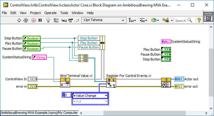 Thin Views The View layer exists to display data to people in a meaningful way, and to provide an interface for interaction. The actor core above handles those two cases elegantly using two framework methods. Bind Terminal Value connects the SystemStatusString to the same name and type on the mediator bus. Register for Control Events will send Value Change messages to this actor whenever the buttons are pressed. The button references are bundled to manipulate the button state and visibility. 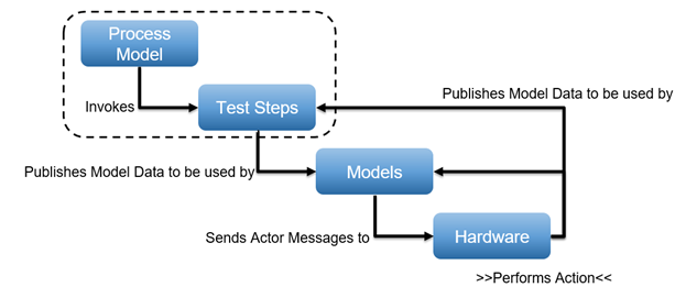 The application control stack Application Control With a bunch of asynchronous actors merrily doing their own thing, we need a way to perform the brewing steps in a synchronous way. The Process Model and test steps operate synchronously. The test steps publish model data onto the mediator bus that the asynchronous models respond to. The models then send messages as needed to the concrete hardware to perform actions. The results of these actions are published to the mediator bus to be consumed by models, test steps, and/or views. The Test Executive Jon McBee has written an excellent, nearly turing-complete sequencer called @cs/test-executive that you can find over on GPM (That's G Package Manager, a creation of MGI). This project uses it for straightforward, static sequencing, but it is capable of loops, conditionals, and parallelism. To use it, all my process model needs to do is call get next. 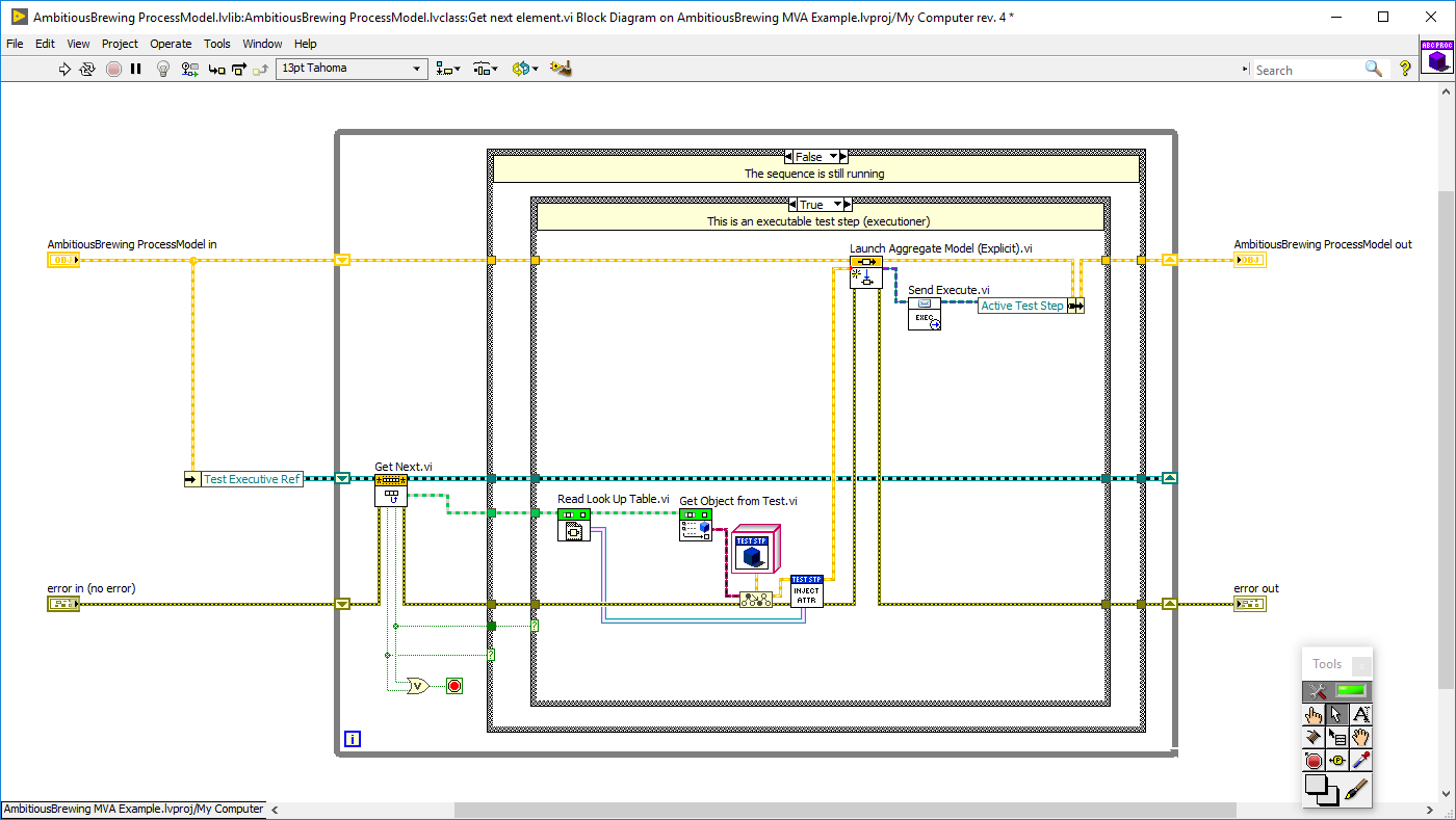 Get next element The process model is completely separate from the flow control in the test executive. It only needs to know which brewing step is next. In get next, it receives the test step object and its attributes, then spins up the step and sends it the execute message. Check it out This code is all open source (MIT license) and is hosted on the Composed Systems Bitbucket. It is a work in progress and I will be continuing to develop this over the next few months as we put the system together. All the Composed Systems packages used to build this project are hosted on GPM. The slides from the presentation can be found on the Composed Systems Presentations page over at www.composed.io. Thank you for reading! Steve Ball is a partner at Composed Systems and is a Certified LabVIEW Architect bent on producing SOLID open-source LabVIEW projects to share with the LabVIEW community.
0 Comments
Leave a Reply. |
Tags
All
Archives
October 2019
LabVIEW Blogs |
 RSS Feed

Powered by the Panda Ant
|